TCP Congestion Control
TCP header Structure:
1. source port
2. destination port
3. sequence number
4. ack number
5. header length
6. flags (SYN, ACK, FIN, PUSH, RST, URG)
7. advertised window size
8. checksum
9. urgent pointer
10. options
11. padding
TCP segment size is limited by the MTU size.
TCP windows size is the total number of octets that can be transmitted before an ACK is received. If the TCP windows size is big enough, multiple segments can be transmitted.
TCP contains four congestion control algorithms:
1. Slow Start
Old TCPs would start a connection with the sender injecting multiple segments into the network, up to the window size advertised by the receiver. This is problematic If there are routers and slower links between the sender and the receiver, because intermediate routers may need to queue the packets, and may run out of space.
The algorithm to avoid this is called slow start. It adds another window to the sender's TCP: the congestion window, called "cwnd". When a new connection is established with a remote host, the congestion window is initialized to the size of one segment. Each time an ACK is received, the congestion window is doubled.
The sender can transmit up to the minimum of the congestion window and the advertised window. The congestion window is flow control imposed by the sender, while the advertised window is flow control imposed by the receiver. The former is based on the sender's assessment of perceived network congestion; the latter is related to the amount of available buffer space at the receiver for this connection.
2. Congestion Avoidance
The loss of a packet typically signals congestion on the network between the source and destination. There are two indications of packet loss: a timeout occurring and the receipt of duplicate ACKs.
Congestion avoidance and slow start are independent algorithms with different objectives. But when congestion occurs TCP must slow down its transmission rate of packets into the network, and then invoke slow start to get things going again. In practice they are implemented together. Slow increases the window size exponentially, and congestion avoidance increases the window size linearly.
Congestion avoidance and slow start require that two variables be maintained for each connection: a congestion window, cwnd, and a slow start threshold size, ssthresh. The combined algorithm operates as follows:
1. Initialization for a given connection sets cwnd to one segment and ssthresh to 65535 bytes.
2. Sender never sends out more than the minimum of cwnd and the receiver's advertised window.
3. When congestion occurs (indicated by a timeout or the reception of 3 or more duplicate ACKs), one-half of the current window size (the minimum of cwnd and the receiver's advertised window, but at least two segments) is saved in ssthresh. Additionally, if the congestion is indicated by a timeout, cwnd is set to one segment (i.e., slow start).
4. When new data is acknowledged by the other end, increase cwnd, but the way it increases depends on whether TCP is performing slow start or congestion avoidance. If cwnd is less than or equal to ssthresh, TCP is in slow start; otherwise TCP is performing congestion avoidance. Slow start continues until TCP is halfway to where it was when congestion occurred (since it recorded half of the window size that caused the problem in step 3), and then congestion avoidance takes over.
3. Fast Retransmit
A duplicate ACK can be caused by a lost segment or just a reordering of segments. TCP assumes that if there is just a reordering of the segments, there will be only one or two duplicate ACKs before the reordered segment is processed, which will then generate a new ACK. If three or more duplicate ACKs are received in a row, it is a strong indication that a segment has been lost. TCP then performs a retransmission of what appears to be the missing segment, without waiting for a retransmission timer to expire.
4. Fast Recovery
After fast retransmit sends what appears to be the missing segment, congestion avoidance, but not slow start is performed. This is the fast recovery algorithm. It is an improvement that allows high throughput under moderate congestion, especially for large windows.
The reason for not performing slow start is that the receiver can only generate the duplicate ACK when another segment is received, which means there is still data flowing between the two ends, and TCP does not want to reduce the flow abruptly by going into slow start.
More information can be found at:
RFC 2001
RFC 2581
RFC 1323
Wireless LAN
T1 - line coding, framing and signaling
T1 uses either AMI (Alternate Mark Inversion) or B8ZS (Binary 8 Zero Substitution) line coding. A CSU/DSU is the device that converts the input digital signal into T1 line code.
A T1 frame contains 24 8-bit time slots (also called channels) and a framing bit, which makes 193 bits in total, and transmit 8000 frames per second.
T1 framing is either D4 Super Frame (SF) or Extended Super Frame (ESF). The difference is the number of signaling bits. A D4 SF is the packaging of 12 frames, while an ESF has 24 frames and additional signaling bits means more control capabilities. Two mechanisms can be activated when using D4 SF or ESF: synchronization mechanism, which is always activated, and signaling mechanism, which is optional.
T1 can support voice, dedicated data or ISDN PRI:
On a dedicated data T1 circuit, the signaling is not needed and therefore is disabled. SF or ESF framing bits are only used for synchronization.
On a voice T1 circuit, however, signaling is required. SF/ESF framing bits are used for both synchronization and signaling. In-band signaling, CAS (channel associated signaling, also called robbed-bit signaling) is used because the voice quality will not be impacted by losing the least significant bit.
On a ISDN PRI circuit, a D channel is used for out-of-band signaling, which is also called CCS (common channel signaling).
CAS signaling can be either Ground/Loop or E&M Wink/Delay/Immediate.
When using the T1 interfaces several modes of operation are available. These modes are listed below:
1. Unframed (UNF): A stream of bits at 1544 Kbs. No channels are associated to any specific group of bits. None of the mechanism described above is used.
2. Superframe (SF): Data transferred using the SF format.
3. SF + CAS
4. ESF
5. ESF + CAS
6. ESF + FDL (Facility Data Link provides maintenance and supervisory control)
7. ESF + CAS/CRC/FDL (CRC provides error monitoring capability)
8. CCS: Can be used in each of the framed formats, by dedicating one channel (usually TS-24) for delivering the signaling messages, in a predetermined protocol.
Configuring Channelized E1 and T1
North American T1 Facilities
PSTN
SS7 is also known as Common Channel Signaling (CCS). It runs on a separate network that consists of Service Switching Point (SSP), Signal Transfer Point (STP) and Service Control Point (SCP).
While CAS and Out-of-Band Signaling such as PRI are used on the edge of the PSTN network (between the CO switch and the PBX), SS7 is used on the core.
SONET is a layer 2 protocol, similar to ATM, but more efficient. IP over SONET needs to encapsulate IP into PPP first.
ATM network can be built either upon fiber optic directly, or on top of SONET, which allows service providers to provide ATM service through a traditional SONET network.
SONET is purely TDM based. Currently a fiber supports up to OC192 (10Gbps) data transmission rate with a single wavelength. With WDM/DWDM we essentially create multiple SONET rings on a single fiber (up to 128 wavelengths), and therefore multiple ADM is needed. With proper traffic grooming, we can reduce the number of ADMs therefore reduce the cost.
Voice Signaling: Loop-Start; Ground-Start; E&M
Loop-Start; Ground-Start and E&M can be either analog or digital. When they are used as digital signaling, the different state is represented by the A, B, C, D bits of CAS.
The main difference between ground-start and loop-start signaling is that ground-start requires ground detection to occur in both ends of a connection before the tip and ring loop can be closed. This ensures that both ends are ready before the call can start.
E&M does not creat a loop, it uses two separate lines - Ear Lead and Mouth Lead. And the voltage change on the E-Lead or M-Lead indicates the change of state.
More information can be found at:
Voice Signaling and Control
Understanding One-stage and Two-stage Dialing
Understanding DID
SONET/WDM Taffic Grooming
Dialup Services
More information can be found at:
Configuring PRI for Incoming Async and ISDN Calls
Configuring a Modem on the AUX Port for EXEC Dialin
Configuring PPP Dialin with External Modems
IP Services and Management
Switching
VTP
Three VTP modes: server mode; client mode and transparent mode.
Extended VALNs can only be added under the transparent mode.
Trunking
802.1Q by default does not tag the native VLAN. ISL doesn't have native VLAN, it tags all VLANs.
Cisco switches use DTP to negotiate trunk mode and encapsulation mode.
Etherchannel
Two etherchannel negotiation protocols: Cisco's proprietary PAgP and industry standard LACP.
Two switches will form etherchannel with the following modes:
on - on (no PAgP or LACP)
auto - desirable (desirable side initiates PAgP negotiation)
desirable - desirable
active - passive (active side initiates LACP negotiation)
active - active
Connfiguration on all channel member interfaces has to be identical in order to form the etherchannel.
By defult etherchannel load balance base on source addresses. Depending on the traffic pattern, this can be changed to destination based to achieve better load balancing.
Spanning Tree
Spanning Tree has three steps:
1. Select Root Bridge
A bridge ID consists of bridge priority and bridge MAC address. The switch with the lowest bridge ID becomes the root.
2. Select Root Port
Port cost, upstream neighbor's bridge ID, port priority, and port ID are used to select the root port (in that order).
Note: when selecting root port, it is upstream neighbor's port priority that we are comparing. So the port priority affects downstream neighbor, while port cost affects the local switch itself and all its downstream switches, because port cost is accumulative.
3. Select Designated Port
Spanning tree root guard will block a port from which a superior bpdu is received. It may also prevent spanning tree problem when there is a uni-directional fiber failure.
When using spanning tree port-fast, should also enable bpdu guard on the port.
802.1x
Two steps to configure 802.1x:
1. Use aaa authentication dot1x default group radius or tacacs+ in the global mode.
2. on the switch port enter dot1x port-control auto
Private VLAN
Private VLAN, also known as protected ports, is normally used in DMZ. Protected ports cannot communicate with each other, however they can communicate with unprotected ports in the same VLAN.
Switch(config)# interface fastethernet0/1
Switch(config-if)# switchport protected
Port Blocking
It's used to prevent unknown unicast or multicast traffic from being forwarded from one port to another. Port blocking can be configured on a protected or nonprotected port.
Switch(config)# interface gigabitethernet0/1
Switch(config-if)# switchport block multicast
Switch(config-if)# switchport block unicast
Storm Control
Storm control prevents traffic on a LAN from being disrupted by a broadcast, a multicast, or a unicast storm on one of the physical interfaces.
Switch(config)# interface fastethernet0/1
Switch(config-if)# storm-control unicast level 87 65
Switch(config)# interface fastethernet0/1
Switch(config-if)# storm-control broadcast level 20
Port Security
Port security is used to restrict input to an interface by limiting and identifying MAC addresses of the stations allowed to access the port.
Access Control List
Switch ACLs include IP ACLs; MAC ACLs - which can be used to filter non-IP traffic; and VLAN ACLs.
Below is an sample configuration of IP ACL:
Switch(config)# access-list 102 permit tcp any 128.88.0.0 0.0.255.255 gt 1023
Switch(config)# access-list 102 permit tcp any host 128.88.1.2 eq 25
Switch(config)# access-list 102 permit icmp any any
!
Switch(config)# interface gigabitethernet0/1
Switch(config-if)# ip access-group 102 in
And here is the MAC ACL configuration:
Switch(config)# mac access-list extended mac1
Switch(config-ext-macl)# deny any any decnet-iv
Switch(config-ext-macl)# permit any any
!
Switch(config)# interface gigabitethernet0/3
Switch(config-if)# mac access-group mac1 in
Finally the VLAN ACL configuration, remember there is an unexplicit deny any at the end:
Switch(config)# ip access-list extended SERVER1_ACL
Switch(config-ext-nacl))# permit ip 10.1.2.0 0.0.0.255 host 10.1.1.100
Switch(config-ext-nacl))# permit ip host 10.1.1.4 host 10.1.1.100
Switch(config-ext-nacl))# permit ip host 10.1.1.8 host 10.1.1.100
!
Switch(config)# vlan access-map SERVER1_MAP
Switch(config-access-map)# match ip address SERVER1_ACL
Switch(config-access-map)# action drop
Switch(config)# vlan access-map SERVER1_MAP 20
Switch(config-access-map)# action forward
Switch(config-access-map)# exit
!
Switch(config)# vlan filter SERVER1_MAP vlan-list 10-20
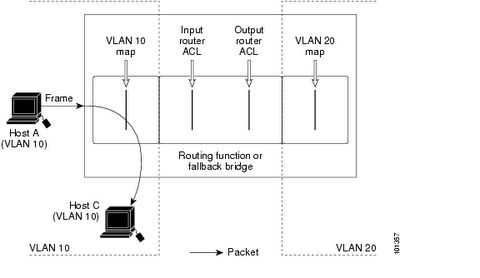
Note: VLAN ACL is processed before the router ACL, below is the process flow.
UDLD
UDLD can be used to detect uni-directional fiber problem. UDLD has two modes: enable mode and aggressive mode.
Fallback Bridging
Fallback bridging is to support non-routable legacy protocols across different VLANs.
More information can be found at:
Catalyst 3550 Configuration Guide
QoS
ToS, Precendence and DSCP Mapping
ToS/Precedence and DSCP are both using the 8-bit Type of Service field in the IP header.
ToS/Precedence:
P2 P1 P0 T2 T1 T0 U U
DSCP (DiffServ Code Point):
D5 D4 D3 D2 D1 D0 U U
where T2 is Delay, T1 is Throughput, T0 is Reliability, U is unused.
DiffServ utilizes the same IP precedence bits, plus offers finer priority granularity with the next three bits (D0 is always 0, so it's actually two bits).
D5, D4 and D3 defines the class - 101 is class EF and 001, 010, 011, 100 are class AF.
Class EF doesn't have subclass, but class AF support subclass using D2 and D1 bits.
For instance af21 is 010010, basically af2 is the main class, while 1 is the subclass (Note: the last bit is D0, which is always 0). Below is the complete mapping list.
<0-63> Differentiated services codepoint value
af11 Match packets with AF11 dscp (001010)
af12 Match packets with AF12 dscp (001100)
af13 Match packets with AF13 dscp (001110)
af21 Match packets with AF21 dscp (010010)
af22 Match packets with AF22 dscp (010100)
af23 Match packets with AF23 dscp (010110)
af31 Match packets with AF31 dscp (011010)
af32 Match packets with AF32 dscp (011100)
af33 Match packets with AF33 dscp (011110)
af41 Match packets with AF41 dscp (100010)
af42 Match packets with AF42 dscp (100100)
af43 Match packets with AF43 dscp (100110)
cs1 Match packets with CS1(precedence 1) dscp (001000)
cs2 Match packets with CS2(precedence 2) dscp (010000)
cs3 Match packets with CS3(precedence 3) dscp (011000)
cs4 Match packets with CS4(precedence 4) dscp (100000)
cs5 Match packets with CS5(precedence 5) dscp (101000)
cs6 Match packets with CS6(precedence 6) dscp (110000)
cs7 Match packets with CS7(precedence 7) dscp (111000)
default Match packets with default dscp (000000)
ef Match packets with EF dscp (101110)
FR Traffic Shaping:
Traffic shaping will initially allocate full tokens to the interface, after they are used up, tokens will have to be earned.
FR traffic shaping’s CIR is actually the target rate, not provider’s CIR, normally it’s greater than provider’s CIR.
minCIR (if not specified, by default minCIR = 1/2 CIR) is provider’s CIR. minCIR should only be used in conjunction with adaptive shaping.
Bc (bits) = CIR * Tc
Be (bits) is actually the size of a token bucket, which saves all the unused Bc bits from previous intervals (initially Be bucket is full). If Be bucket is full, no more unused Bc bits can be saved. The available bits in the Be bucket is the number of bits that can be sent out above Bc during any given interval. Be can only be used once per second - during the first Tc in the 1-second period.
Tc by default is 1/8 second on a link slower than 640Kbps, and 1/16 second on a link faster than 640Kbps. Maximum Tc valus is 125ms, and minimum Tc value is 10ms.
Note: when there is a time sensitive traffic, use the smallest Tc value to prevent high priority packets from waiting a long interval for the next Tc.
Traffic shaping has its own queue, which is separate from the outbound interface queue. The traffic shaping queue can hold 40 packet by default (the range is 1-1024).
When there is a congestion, the receiver will get packets with FECN bit marked, and the returning traffic back to the sender will have the BECN bit marked. The problem is if the receiver never sends any packet back, the sender won’t get any BECN.
frame-relay fecn-adapt command forces the receiver to send a packet back whenever it receives a FECN packet.
In the below example, CLASS_1 will be applied on PVC 504, CLASS_2 will be applied on PVC 503, and CLASS_3 will be applied on PVC502.
interface Serial 0/0
encapsulation frame-relay
frame-relay traffic-shaping
frame-relay class CLASS_1
!
interface Serial 0/0.1 point-to-point
ip address 10.0.1.1 255.255.255.0
frame-relay interface-dlci 504
!
interface Serial 0/0.2 multipoint
ip address 10.0.2.1 255.255.255.0
frame-relay class CLASS_2
frame-relay map 10.0.2.2 502 broadcast
frame-relay map 10.0.2.3 503 broadcast
frame-relay interface-dlci 502
class CLASS_3
More information can be found at:
Frame Relay Traffic Policing
ATM Traffic Shaping
Route Redistribution
BGP
How does BGP prevent routing loop?
· Check AS path for the eBGP routes
· BGP routes learned from an iBGP neighbor will not be advertised to another iBGP neighbor (unless it’s a route reflector)
OSPF
How OSPF works:
OSPF routers send out Hello packets every 10 seconds (30 seconds for NBMA and Point-to-Multipoint networks) to negotiate a two-way neighbor relationship (in order to become neighbors, they must agree on certain parameters such as Hello interval and network types). A neighbor is declared down if no Hello packet is received within the dead-interval (by default 4 x Hello-interval).
Adjacency is not necessarily established between all two-way neighbors (e.g. DOthers don't establish adjacency with each other).
LSAs are sent to the adjacent neighbors. Neighbors first forward the received LSAs out to their own adjacent neighbors, then create their own topology databases based on these LSAs. This repeats until the LSAs are flooded throughout the whole area.
Every router in the area builds SPF tree based on its own topology database and calculate the shortest path to every known destination.
LSAs are retransmitted every 30 minutes with a incremental sequence number even there is no network topology change. LSAs will timeout after 60 minutes without receiving refresh LSAs.
OSPF multicast addresses:
· 224.0.0.5 is All OSPF routers
· 224.0.0.6 is All DRouters (DR and BDR)
OSPF network types:
1. Broadcast Network
· elects DR and BDR
· OSPF routers only become adjacent with DR/BDR
· Hellos are sent to 224.0.0.5
· LSAs are sent to 224.0.0.6, then DR floods them to 224.0.0.5
2. Poin-to-Point Network
· no DR/BDR election
· neighbors always become adjacent
· both Hellos and LSAs use 224.0.0.5
3. Point-to-Multipoint Network
· no DR/BDR election
· multiple remote sites terminating on the same interface
· creates a /32 host route for each neighbor (no need for complete frame-relay mapping)
· essentially creates a group of point-to-point adjacencies
· better alternative to NBMA
4. Point-to-Multipoint non-broadcast Network
· no DR/BDR election
· variation from point-to-multipoint (it allows defining different cost for different neighbors)
· neighbors need to be explicitly defined on the hub
5. Non-broadcast Multi-access Network (NBMA)
· elects DR and BDR
· DR has to have direct pvc to every neighbor, need to explicitly set priority to 0 on all DOther routers
· neighbors need to be explicitly defined on the DR (DOther doesn’t need neighbor definition)
· essentially the DR will forward LSA among the Dothers
· all OSPF packets are unicast
6. Loopback Network
· by default creates /32 host route for loopback interfaces
7. Virtual Link Network
· treated as point-to-point network
· cannot run across a stub area
· must be terminated on router ID instead of just any physical interface address.
· different from tunneling in that the transitional routers will see the real destination address, which means the routers on the path in the transitional area must know how to route the packet
· A virtual ink essentially creates two ABRs, and the routers on the path need to know how to reach the destination, therefore a virtual link cannot be built across a stub area.
Note: Network types with DR/BDR are able to establish adjacency with each other (may need to adjust timer), and network types without DR/BDR are able to establish adjacency with each other. However they cannot mix match.
When using non-broadcast network type, a complete frame-relay mapping statement has to be explicitly defined on all routers on the same NBMA subnet (even if there is no direct pvc between the two routers) because spoke A will see sopke B (not the DR) as the next hop for spoke B’s sunbets.
Complete frame-relay mapping statement is not required for point-to-multipoint network type because it creates a /32 host route for each router, and spoke A’s next-hop for spoke B’s subets is the hub (because a point-to-multipoint network is treated as a group of point-to-point networks).
OSPF interface state machine:
OSPF neighbor state machine:
1. Down
2. Init
3. Two-way
4. Ex-Start
5. Exchange
6. Loading
7. Full
OSPF area types:
· Transitional area
· Backbone area
· Stub area (doesn’t accept any external routes, only inter-area routes)
· Totally stubby area (doesn’t even accept inter-area routes, only a default route)
· NSSA area (only accept its own external routes and inter-area routes)
· Totally NSSA area (only accept its own external routes and a default route)
Note: ASBR of a NSSA area uses a P-bit (pass bit) to notify the ABR whether or not to translate the type 7 NSSA external LSAs into type 5 external AS LSAs and flood them throughout other areas. Cisco implementation always set P-bit to 1.
OSPF LSA types:
type 1 – router link LSA
type 2 – network link LSA (generated by DR)
type 3 – network summary LSA
type 4 – ASBR summary LSA
type 5 – external AS LSA
type 6 – MOSPF LSA
type 7 – external NSSA LSA
OSPF metric:
cost = 10^8/bw
cost is only considered in one-direction (only the outgoing interfaces on the path towards the destination will be considered, which means the router interfaces at each end of a link can have different costs).
OSPF route types (in the order of preference):
intra-area routes
inter-area routes
type 1 external routes
type 2 external routes
OSPF packet types:
Hello packet
LSA request packet
LSA update packet
LSA acknowledgement packet
Database description packet (used during ExStart state)
· I-bit (indicates the first DD packet)
· M-bit (indicates more DD packets to come)
· M/S-bit (indicates Master of the database sync process)
OSPF stub router:
Similar to EIGRP stub router, the stub router will change its interfaces in the non-stub areas to infinity while keep the stub area interfaces unchanged.
OSPF Demand Circuit:
OSPF demand circuit suppresses both Hello packets and LSA refresh packets (LSAs learned across it will not age), but still floods LSA updates across it when there is a network topology change.
More information can be found at:
OSPF Stub Router
IS-IS
IS-IS LSP packets are not IP packets (unlike OSPF LSAs). Therefore on the BRI, ATM and Frame Relay interface, we need to define layer 2 mapping for CLNS protocol.
IS-IS LSP’s MaxAge is 20 minutes, and Refresh interval is 15 minutes.
Level-1 and Level-2 Domain:
· IS-IS level-1 and level-2 domains are different from OSPF areas. A level-2 domain can have more than one areas in it.
· A network can have multiple level-1 domains but only one level-2 domain.
· A level-1 domain can only have one area. It is similar to OSPF Totally NSSA area. It will see intra-area routes, a default route from the L1/L2 router for inter-area destinations, and external routes.
· A level-2 domain can have multiple different areas. It is similar to OSPF backbone area. And level-2 domain must be contiguous.
Note: Level-1 can learn routes in a different area through IS-IS route leaking.
Areas and Level-1 and Level-2 Routers:
· IS-IS area is not defined on the interface but on the router itself using a CLNS NET address.
· A level-1/level-2 or level-2 router is similar to OSPF ABR.
· A level-1 router can be a ASBR but not ABR.
· A level-2 router can have adjacency with other level-2 routers in different areas
· A level-1 router can only establish adjacency with level-1 routers in the same area.
· Two types of IS-IS adjacency: L1-L1 and L2-L2. Adjacency cannot be established between a level-1 router and a level-2 router.
Note: When redistributing other routing protocols into IS-IS, you can choose whether to redistribute into level-1 or level-2.
CLNS NET Address:
· A CLNS NET address consists of three parts: area_id.system_id.nsel, in which system_id is 6 Bytes and N-Selector (nsel) is 1 Byte and its value is always 0x00.
· A CLNS NET address always starts with a single Byte (e.g. 000A.0000.0000.0001.00 is not valid, but 00.000A.0000.0000.0001.00 is valid).
· A CLNS NET address is in hex-decimal format. (so area 10 should be 0x0A).
· A CLNS NET address length has to be consistent throughout the domain.
· The first Byte of area_id is AFI, an AFI value of 0x49 means it’s private IS-IS address.
· A router can only have one CLNS NET (Network Entity Title) address.
Network Types:
· Broadcast network (default type for any multipoint interface)
· Point-to-Point network
Note: Only interfaces with matching network types can establish adjacency. IS-IS does NOT support NBMA network, tunnel has to be created for this scenario.
Hello Packet Types:
· Level-1 LAN Hello
· Level-2 LAN Hello
· Serial Hello (level-1 and level-2 Hello on a point-to-point segment use are same)
Note: IS-IS Hello packets will use padding to increase the packet size to MTU, and this may cause problem when using tunneling. This behavior can be disabled.
Designated Intermediate System:
· Unlike OSPF, IS-IS router on a broadcast/multi-access network will establish adjacency with not only the DIS, but all of its neighbors.
· IS-IS doesn’t have BDR.
· IS-IS DIS election is preemptive.
· DIS is responsible for advertising the network out to the whole domain.
LSP Option Bits:
· ATT bit – attach bit, if set to 1 means the originating router is attached to multiple areas.
· OL bit – overload bit, setting OL bit to 1 turns the originating router into a stub router, it will not be used as a transit router.
Three ways to include an interface into ISIS:
1. Enable isis on the interface
2. Redistribute connected interface
3. Use passive-interface in IS-IS for the interface
IS-IS Metric:
The original metric is 1-63, and new metric is 1-16777214. This can be controlled by using the metric-style
IS-IS sample configuration:
router isis
net 49.000A.0000.0000.0001.00
!
interface Serial 0/0
encapsulation frame-relay
frame-relay map clns 301 broadcast
ip router isis
!
Note: IS-IS has to be enabled under global config as well as under interface config.
EIGRP
EIGRP stub routing
EIGRP stub routing will suppress transit eigrp updates, it receives updates but will not passon to downstream neighbor.
EIGRP route summarization
EIGRP allows you to summarize route on the interface level with command
ip summary-address eigrp 100 144.1.0.0 255.255.0.0
it creates a static route for the summarized network pointing to the null0 interface.
EIGRP metric
[K1*BW + (K2*BW)/(256-Load) + K3*Delay] * [K5/(Reliability + K4)]
The default constant values are K1 = K3 = 1 and K2 = K4 = K5 = 0.
EIGRP metric can also be manually changed using offset-list.
EIGRP timers
ip hello-timer eigrp 100 10
ip hold-timer eigrp 100 75
EIGRP distance
distance eigrp command can assign different distances for internal eigrp routes learned from different neighbors (but for the internal eigrp routes ONLY, can't use different distances for external routes learned from different neighbors).
Default route redistribution
Need to explicitly allow EIGRP to allow default route redistribution on the default route origin router.
default-information allowed inout
Load-balancing can be controlled with variance.
More information can be found at:
Configuring EIGRP
RIP v2
Default Route and Classless Routing
By default, if a router receives a packet destined for a subnet it does not recognize, the router discards the packet. However when classless routing is enabled, instead of discarding the packet, the router forwards the packet to the best supernet route.
There are three ways to define gateway of last resort:
ip defaul-gateway
ip default-network
ip route 0.0.0.0 0.0.0.0
The ip default-gateway command differs from the other two commands. It should only be used when ip routing is disabled on the Cisco router.
The ip default-network command is classful. It must be issued using the major net, in order to flag the candidate default route. RIP, IGRP and EIGRP understand default-network, and will automatically redistribute it out.
More information can be found at:
Route Selection in Cisco Routers
Multicast
Multicast Addresses
Multicast address is 224.0.0.0 - 239.255.255.255, within which 224.0.0.0 - 224.0.0.255 are used for LAN multicast. 239.0.0.0 - 239.255.255.255 are private multicast addresses similar to RFC 1918 addresses.
Multicast address are class D addresses, therefore there are 28 bit effective address space. However ethernet only allocates half of an OUI address space, which is 23 bits (01:00:5E:0xxx xxxx.xx.xx), for multicast. Therefore multiple multicast IP addresses can be mapped to the same ethernet MAC address.
IGMP v1 and IGMP v2
IGMP is used by hosts to report their group membership to the neighboring multicast routers. And IGMP Snooping and CGMP are used by the switches to determine the group membership of the switch ports.
* IGMP v1 Query-Response Process
1. ICMP Querier router periodically sends out membership query to All-Hosts address 224.0.0.1 on the local subnet.
2. A host responds by sending membership report message to the group address it's a member of. And other hosts within the same group will suppress their report.
IGMP v1 doesn't have join message, it uses unsolicited membership report message to join a group. IGMP v1 doesn't have querier election process, the PIM or DVMRP designated router is automatically used as IGMP v1 querier router.
* IGMP v2 Leave Process
1. A host sends a leave group message to All-Routers address 224.0.0.2.
2. The querier sends out a group-specific query to the group address.
3. If there is any other host left in the group, it will respond to the group-specific query.
IGMP v2 has Querier Election, Leave Group Message and Group-specific Query.
Multicast Routing Protocols
PIM, DVMRP, CBT and MOSPF are the multicast protocol used among the routers.
* Dense mode multicast routing protocols: DVMRP and PIM-DM.
* Sparse mode multicast routing protocols: PIM-SM and CBT.
* Link-State multicast routing protocols: MOSPF.
MOSPF is similar to Dense mode protocols. But instead of flooding and prunning multicast traffic, it floods out LSAs that identify the whereabouts of group members, i.e. receivers, in the network.
Cisco IOS does not support complete DVMRP, but PIM interoperates with DVMRP. And Cisco PIM routers will propagate DVMRP routes and use the DVMRP routing table for RPF.
Multicast RPF check is separate from the PIM, multicast routers may use unicast routing table, DVMRP multicast routing table or Multicast BGP routing table for RPF verification.
(S,G) is a source tree, also called Shortest Path Tree (SPT). It is used by Dense mode protocols.
(*,G) is a shared tree from the RP. It is used only by Sparse mode protocols.
PIM-DM Assert is similar to Spanning Tree's designated port election, it determines which PIM router on the LAN segment will be the forwarder for the incoming multicast traffic.
PIM DR (Designated Router) is different concept. It determines which PIM router on the LAN segment will be forwarding the join message to the RP to build the shared tree.
DLSW and Bridging
ISDN Dial-On-Demand and PPP
ISDN
Basic ISDN configuration:
interface bri0/0
isdn switch-type basic-ni
isdn spid1 5272014
ip address 144.1.45.4 255.255.255.0
dialer map ip 144.1.45.5 broadcast 5272015
dialer-group 1
!
dialer-list 1 protocol ip permit
when a physical BRI interface uses PPP encapsulation, it becomes a point-to-point interface and therefore doesn't need dialer map.
interface bri0/0
isdn switch-type basic-ni
isdn spid1 5272014
encapsulation ppp
ip address 144.1.45.4 255.255.255.0
dialer string 5272015
dialer-group 1
PPP
PPP authentication is unidirectional and is done independently by the two parties of the call. Two sides may use different authentication protocol. We are going to demonstrate this in the following examples.
1. A requires B to authenticate itself, but B doesn't require A to authenticate.
Router-A:
username Router-B password CISCO
!
interface bri0/0
encapsulation ppp
ppp authentication chap
Router-B:
username Router-A password CISCO
!
interface bri0/0
encapsulation ppp
alternatively we can configure the CHAP password on Router-B's interface instead of global config
interface bri0/0
encapsulation ppp
ppp chap password CISCO
2. A uses CHAP to authenticate B and B uses PAP to authenticate A:
Router-A:
username Router-B password CISCO-2
!
interface bri0/0
encapsulation ppp
ppp authentication chap
ppp pap sent-username Router-A password CISCO-1 (this is required for pap auth responder)
Router-B:
username Router-A password CISCO-1
!
interface bri0/0
encapsulation ppp
ppp authentication pap
ppp chap password CISCO-2
Note: in the first example, even though only A requires authentication, password has to be configured on both routers. CHAP password has to match, because both parties creates a hash with it, so it's like a shared secret. However PAP password doesn't have to match on the two routers. PAP requires user name and password to be defined explicitly. See example below:
Router-A:
username Router-B password CISCO-2
!
interface bri0/0
encapsulation ppp
ppp authentication pap
ppp pap sent-username Router-A password CISCO-1
Router-B:
username Router-A password CISCO-1
!
interface bri0/0
encapsulation ppp
ppp authentication pap
ppp pap sent-username Router-B password CISCO-2
ppp authentication chap [callincallout] uses the callin or callout keyword to authenticate only inbound or outbound calls.
Use no peer neighbor-route command to remove the /32 host route automatically added by PPP for the remote end host. This feature was originally designed to support dialup ISP - so that clients from different subnets can dial in the same dialer interface, and the hub router doesn't need the static routes for the remote clients. However this feature may cause OSPF On-demand circuit to keep the ISDN call up.
PPP can also assign IP address to the remote end router using ip address negotiated command.
When using OSPF with ppp multilink, you need to hardcode bandwidth. Otherwise when the second B channel is activated/deactivated, OSPF will recalculate.
ppp reliable-link and ppp quality command will monitor packet loss and line error.
PPP Callback and ISDN Callback
-PPP Callback Server-
interface bri 0
ip address 7.1.1.7 255.255.255.0
encapsulation ppp
dialer callback-secure (optional, it drops inbound calls that don't require callback)
dialer enable-timeout 2
dialer map ip 7.1.1.8 name atlanta class DIAL1 81012345678901
dialer-group 1
ppp callback accept
ppp authentication chap
!
map-class dialer DIAL1
dialer callback-server username
-PPP Callback Client-
interface bri 0
ip address 7.1.1.8 255.255.255.0
encapsulation ppp
dialer map ip 7.1.1.7 name dallas 81012345678902
dialer-group 1
ppp callback request
ppp authentication chap
Callback can also be achieved on the ISDN level using ISDN callback. ISDN callback happens before PPP negotiation, therefore there is no charge for the first call.
int bri 0/0
isdn caller 5272015 callback
Note: we can also use wildcard character x for instance isdn caller 527201x callback. And this command is also used for call screening besides callback.
When a physical BRI interface is associated with multiple dialer interfaces, we can use PPP authentication to decide which dialer interface an incoming call should be bound to.
interface dialer 1
ip address 10.0.0.1 255.255.255.0
encapsulation ppp
dialer pool 1
dialer remote-name Rack1R4
dialer string 5272014
dialer-group 1
ppp authentication chap
!
interface dialer 2
ip address 10.0.1.1 255.255.255.0
encapsulation ppp
dialer pool 1
dialer remote-name Rack1R5
dialer string 5272015
dialer-group 1
ppp authentication chap
or we can use ISDN caller screening feature to bind the incoming calls:
interface dailer 1
isdn caller 5272014
!
interface dialer 2
isdn caller 5272015
Dial-On-Demand Backup
There are three dial backup methods:
1. Backup Interface
2. OSPF On-demand Circuit
3. Dialer Watch
Note: The backup interface will not work if the main interface is manually shutdown.
When using dialer watch, the watched route must be mapped to a layer 2 dialer string.
Useful commands:
show isdn status
show isdn active
isdn test call interface bri0/0 <remote_end_spid>
isdn test disconnect interface bri0/0 all
debug isdn q931debug ppp negotiation
Certificate
![]()